


Inside The Helix Geometry.
I had been sharing my thoughts and designs via emails, with like minded DIYer Yordan Yanakiev of Bulgaria.
In one email, Yordan reported that he had experienced an improvement in sound quality simply by winding the helix in the opposite direction to that initially shown shown on this site, so I decided to investigate.
Putting my photography skills to work I took the following images in an attempt to account for a reason as to why such a noticeable improvement might be experienced, simply by reversing the direction of the Helix winding.
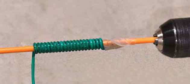
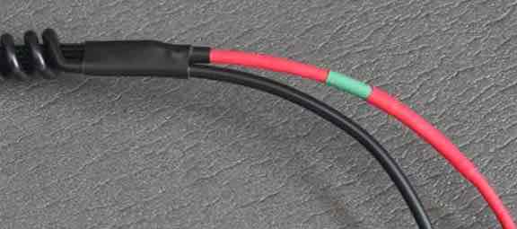
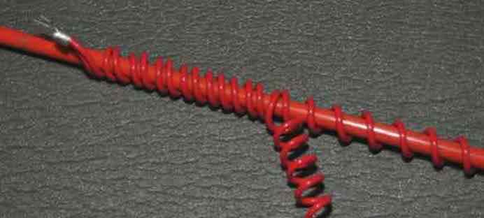
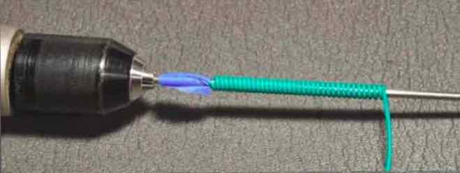
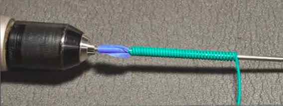
This first image (below) shows the helix being wound in (let’s call it) a clockwise direction.
![image[8]](page6_blog_entry79-image005b8005d.jpg)
As you can see, the actual strands of the wire used in the Helix, are crossing the strands in the signal wire at approximately 70 degrees
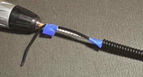
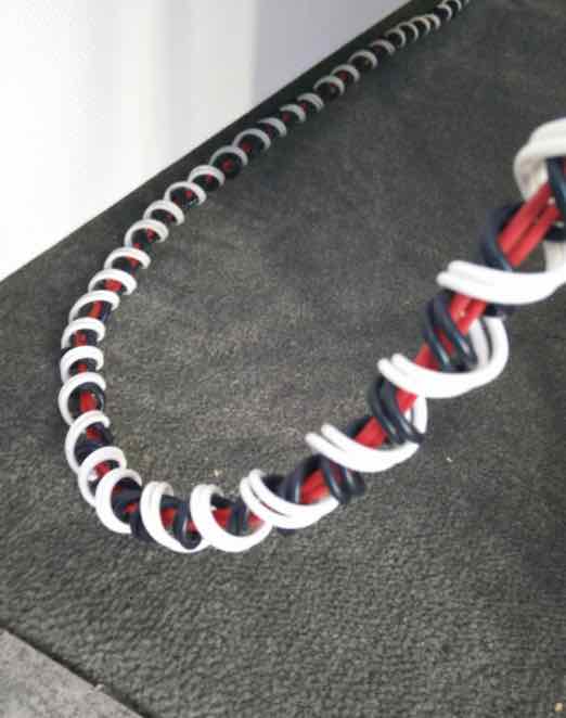
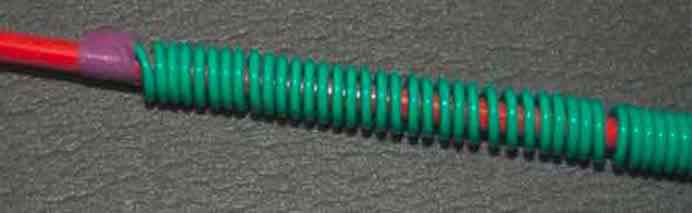
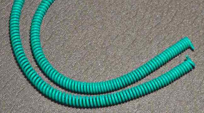
However - if the helix is wound in the opposite counter clockwise direction (see below), then the angle of the individual strands is much closer to the desired 90 degree angle in order to minimize induced noise even further.
![image[12]](page6_blog_entry79-image005b12005d.jpg)
Please Note: that before deciding to wind the Helix in a particular direction, you must take into consideration the direction of the twist of the strands in the actual wire you are using
- in this case, the strands have been twisted in (let’s call it) a clockwise direction
- If the wire had a counter clockwise twist - then the helix should be wound in a Clockwise direction to achieve the 90 degree angle.
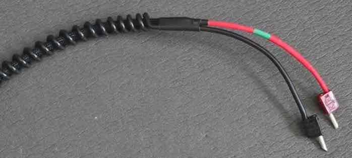
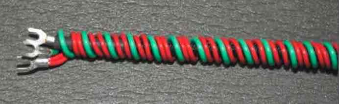
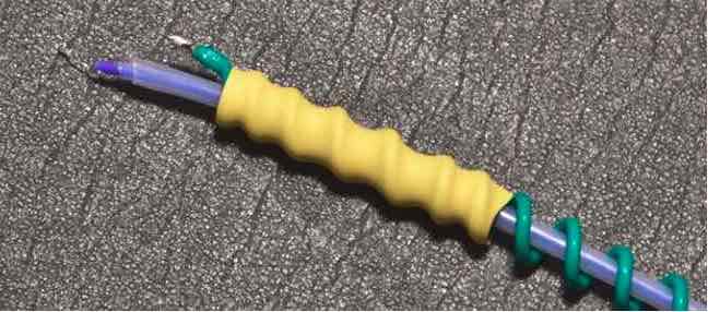
This image shows how to wind both the neutral/ground conductors of each and every Helix cable, i.e. provided you are using a wire that has strands twisted in a CLOCKWISE direction as indicated in the images above.
- If the wire used has the strands twisted in the opposite direction, then the Helix should be wound in the opposite direction to that indicated in the above image
This initially included myself, after all, how much of an improvement could this possibly make???
Well, after converting all of my own cables to the counter clockwise twist I was completely surprised to find that the changes were very discernible and contributed to a much improved image and very much improved clarity.
How Anal Do You Wanna Get?
In the images above, I have used the same wire for both live/signal and neutral conductors and as such the twist of the individual strands in both wires is the same. But what if the strands in just ONE wire is twisted in the opposite direction, which direction should the helix be wound in ???
That decision I will leave to the individual.
Personally - I think this level of “detail” is beyond the resolution capabilities of my system, but I felt it should at least be mentioned for those out there that may wish to investigate
Other Observations from Yordan include...
Having had many email conversations with Yordan, he has shared the following observations he experienced, which include:
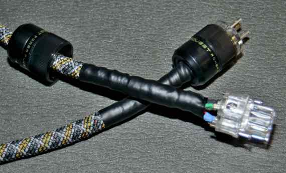
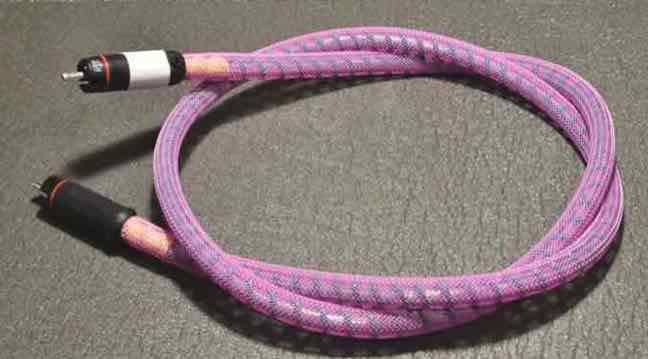
- The cables sound more open when the expandable nylon sleeve i.e. to give the cable a “professional appearance”, is NOT used
- The power cables sounded better without spades
- Personally, on my system I found the spades provided faster dynamics and bass delivery
- avoid using heat shrink tubing where it draws the signal and neutral wires closer together
- To better isolate the signal (or live) wire use teflon tube - not the expandable sleeve as identified in the web site
NOTE: I have tried a couple of things above, but on my system I did not experience the same observations. But as in Yordan’s case, on your system you could observe improvements by following his tips. so give them a try
So, the Proof of the Pudding...
So, to put Yordan’s “Helix direction” findings to the test, I rebuilt built all of my Helix cables, this time with the Helix neutral wound in a counter clockwise direction. with everything else being identical.
Right from the very first track it was apparent that the direction of the helix REALLY DOES MATTER!
The image was larger in all dimensions, with the location of musicians being more precise and with more space around them, details and associated clarity improved, dynamic performance was faster, bass performance was faster with more texture and the mid and upper frequencies revealed a new warmth not previously there.
But Was It Easily Discern-able?
To these old ears - very definitely. I spent over two hours playing the tracks I use to audition cables and components, just so I could hear how much better they sounded with the revised Helix cables.
So there you have it - taking into account the actual direction of the Helix winding has proven beneficial
What if I have already used a Clockwise Helix???
If you would like to correct a cable that has a Clockwise wound helix...
- DO NOT simply pull the Helix coil straight - this will over-twist the strands inside the wire
- Remove the Helix coil from the cable i.e. slide the coil off of the live/signal conductor intact
- Then slide the helix coil onto a suitably sized steel/fibreglass rod - NOTE: you will probably need to compress the coil
- Finally, pull on one end of the coil, allowing the coil to spin around on the rod
- this technique prevents the twisted strands inside the wire from becoming deformed
- You can then rewind the helix in the correct direction without any issues
- The important thing is that you “UNWIND” the helix coil
- Otherwise: it may deform the strands inside the wire, which will impact performance
- NOTE: - power cables are not as sensitive as Speaker cables and interconnects and changing the direction of the Helix does not offer any real discernible improvements in sound quality, so changing their helix direction is not necessary
I have performed this procedure several times and can report that it is actually very easy and a much more effective method than trying to simply straighten a helix coil.
Is all this really necessary?
Well, the choice is yours. The Helix cables will sound extremely good no matter what direction the Helix coil is wound in!
But the improvements achieved on all of my cables by winding the helix in the correct (counter clockwise) direction is the icing on the cake.
Regards - Steve
DIY Speaker Cables - The HELIX Speaker
They’re finally here !!!
Regular visitors to this web site are probably familiar with the Helix Mark V IC and the POWER Helix power cables and now I’ve finally had a chance to develop the Helix Speaker cable.
I’d been procrastinating about making a Helix geometry speaker cable for some time, mainly because I needed a 10 foot pair of cables.
- Winding a helix neutral of the correct gauge for a 10 foot cable was, for me, a little daunting, but it turned out to be easier than I expected.
So what makes Helix cables work?
It get’s pretty complicated ...
For more information on cable design issues please read the three articles below that talk about the many problems that challenge cables builders.
They will provide a great deal of insight into the many parameters and design techniques employed to build cables that excellent in their performance.
https://www.psaudio.com/article/cables-time-is-of-the-essence-part-1/
https://www.psaudio.com/article/cables-time-is-of-the-essence-part-2/
https://www.psaudio.com/article/cables-time-is-of-the-essence-part-3/
So, how do Helix cables prevent that from happening?
In the Helix design, the neutral conductor is wound around the signal conductor, so the neutral is NEVER parallel to the signal wire.
This minimizes -
- induced noise
- Proximity Effect
- Skin Effect
- Rise Time and Decay Distortions
- Minimize Dielectric influences by using only single conductors for the signal and neutral wires
VOILA! - most “cable related problems” are eliminated !!!
(pretty much)
The Helix Geometry is one of the most noise-free cable geometries available.
It should be applied to ALL cables in a system, resulting in a level of fidelity you probably thought could only be attained by having components costing considerably more.
What will you hear? - for me the most noticeable improvement were the venue acoustics, i.e. the echoes and reverberations that surround each artist and instrument.
At first, it can sound as though you have an echo problem in the room, but I have several tracks where there are no reverberations, so playing those confirmed my room acoustics were perfectly fine.
Other attributes that are clearly audible include clarity, neutrality, dynamic performance, bass depth and control.
But one effect that took a while for me to realize just how much it effects the sound is phasing.
Phasing controls the placement of instruments and artists in three ways.
- Their location within the width and depth of the image
- Their location outside of the speakers
- The appearance of the “projection” of sound around (even behind) the listener e.g. like surround sound
We all know if you connect the speakers out of phase the image becomes muddled and the bass performance drops off.
But varying the phase by small amounts can move the position of instruments and artists within the image. The noise impacts the phase of the signals of both channels differently, resulting in an inaccurate image.
Since the Helix Geometry eliminates most all of the noise created inside the actual cable - you will notice an incredibly precise placement of instrument and artist within the image AND an incredibly large image that melts the boundaries of the listening room and envelops the listener.
Now the speakers are truly “invisible”
PLEASE NOTE: Your system will probably not achieve its full potential by installing just one set of helix cables...
They ALL have to have the helix geometry !!!
How To Make Them...
To determine the “Direction” of the Helix - see Inside The Helix Geometry.
Here are the parts...
- Neutral Conductor: 10 gauge silver plated Mil-Spec wire for the neutral from TAKE FIVE AUDIO (TFA)
- Signal conductor: For the budget conscious - a 16 gauge, or 14 gauge or 12 gauge silver plated Mil Spec wire from TFA
- - personally i have not found any difference between these three different gauges, but some people prefer a heavier gauge,
- But - if no expense is to be spared See Note A: The Signal Conductor below
- 3/8” Black heat-shrink (from TFA)
- 3/16” Red heat-shrink (from TFA)
- One five foot fibreglass rod from home depot
- One set of KLEI™Classic Harmony Banana plugs
- 3/8” Black CPA 100 Adhesive Lined Heatshrink (from TFA)
The neutral conductor should be 2.5 times longer than the signal conductor, although you can experiment with this ratio
The signal sleeve is 12-15” shorter than the signal conductor in order to leave some straight wire for the connectors, but you will require two lengths of sleeve for each cable.
- Allow extra for the outer layer because when it expands it actually shortens
- I allowed an additional 6” for the outer sleeve
So for one 10 ft cable PAIR you need
- 20 ft of signal conductor i.e. 10 x 2
- 37 ft of expandable sleeve,
- 50 ft of neutral conductor.
You will also need around 2 feet of the 3/8 heat-shrink and 3 feet of the 3/16” heat-shrink
NOTE A: The Signal Conductor
- I have listed the Mil-Spec wire as the signal conductor, but this is more for proof of concept or for the more budget conscious readers - but I have found 12 gauge Duelund copper stranded with Polycast insulation provides more details and better image.
- I did consider the Duelund 12 gauge wire with oil/cotton insulation, but I have concerns about the oil possibly drying out, or the effect that humidity might have on it’s capacitance.
Please note: the images below may not reflect the wire identified above.
Cut two equal lengths of the neutral conductor - this should be 2.5 times the length of the signal conductor
Put a very tight 90 degree bend in the conductor and tape to the fibreglass rod
Place the end of the fibreglass rod into the chuck of a variable speed drill
Slowly wind the conductor onto the rod
Once the other end of the conductor is reached - leave 6”-8” of straight conductor
- Slide the signal conductor into the coil
- Stretch the coil to the length of the signal conductor
- Place a piece of the red 3/16” heat shrink over the signal conductor
- Use a piece of the 3/8” adhesive lined Heatshrink to hold the coil to the signal conductor

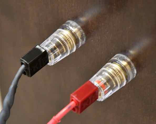
Attach the connectors of your choice - Voila!
I highly recommend the KLEI™Classic Harmony Banana Connector/Adaptors because as you will read, they are exceptionally good and elevates the performance of these cables to a whole new level
These cables provide an extremely high resolution listening experience on all systems - i.e. once burned in
They have extremely low levels of capacitance and inductance, so they are perfect for most systems, especially high current solid state designs.
Please allow 100 hours burn in before making any judgement as to their abilities.
Please note: you are free to try whatever conductors you think might work - but the conductors identified above provide exceptional performance and value.
If you are thinking that 16 gauge is too thin to produce an excellent bass performance, I would suggest you try them first.
You will find their characteristics change during burn-in
- they will sound very good at first
- after around 12 hours their performance will degrade - bass will fall off and some distortion will occur
- after 30 hours they really start to shine
- by 100 hours they are exceptional and will continue to get better
They provide exceptionally detailed and a well controlled deep bass performance
The clarity of these cables is superb, as is the dynamics and imaging
Total cost for a 10 ft pair is around $120 US.
I have compared them to cables costing upwards of a couple of thousand dollars and they are superior across the board.
Hard to believe? Well, if I hadn’t heard it for myself I wouldn’t believe it either!
When I built these cables I was actually not expecting much in the way of improvement over my existing cables, which are excellent performers
I thought they might come close to their level of performance - BUT...
I was Blown Away!!!
But REMEMBER: any system will not achieve its full potential by installing just one set of helix cables...
For optimum perofrmance - ALL cables must have the helix geometry !!!
These cables are truly exceptional, from a fidelity perspective and from a cost perspective they are excellent VALUE!.
For Helix cable spec’s please see Its More Than Just Numbers - Isn't It?
I give them my “Best Bang For The Buck” award.
My Review System:
Custom built turntable with a Soundsmith Denon DL103 phono cartridge mounted on an Audiomods Arm with one piece silver litz harness + KLEI Absolute®Harmony RCA’s
Simaudio MOON LP5.3 RS phono stage
Bluesound Node 2 music server
NAIM 5i integrated amp (with passive pre-section).
Gershman Acoustics Sonogram speakers.
 Give them a try - and - Enjoy The Music!
 ![]()
ADDENDUM:
The development of these cables was something of a collaborative effort. it all started when I responded to a post on the Audiogon Cable Forum by Audiogon member Toddverrone (Todd)
Todd was already familiar with the Helix design since had had already made a couple of my Helix power cables.
We discussed possible approaches, but since I had not actually made a set of Speaker Cables I figured I’d better “Walk the Walk”
And so, the Helix Speaker cables (of the above design) were “born”.
However, since Todd’s speakers were configured for a bi-wire/bi-amp approach he wondered if there was a viable Helix Bi-wire solution in a single cable.
Taking the design above, I modified it in the following manner to incorporate two sets of conductors (LF and HF) into a single cable as follows:
- the two positive conductors would be wound around the fibreglass rod and then straightened out by hand, but leaving the kinks in the conductors in place.
- Each conductor is wound in opposite directions in order to stop them from being able to touch continuously to prevent EMI contamination.
- the two signal conductors would be placed inside two (LF and HF) helix neutral windings, but each neutral would also be wound in opposite directions - again to minimize EMI contamination.
- The net result is what Todd referred to as - one “bad-ass” design
- Perhaps I should name it the - Bad-Ass Helix Bi-Wire ?
As part of the process, Todd had first built a prototype along the lines of the original design above, in order to gauge what the single wired cable would sound like.
This level if fidelity could then be used as a benchmark for comparison to the Bi-wired version.
Todd also used a high grade silver plated copper conductor for the bi-wire version
Final conductor details:
Signal Conductor
- One LF 12 awg conductor and One HF 14 awg conductor with a “kinky helix” wind in opposite directions,
- both are silver plated copper in ptfe from take five audio.
- Dual LF 12 awg silver plated copper conductors in ptfe for the inner helix
- Dual HF 14 awg silver plated copper conductors in ptfe for the outer helix
- The 14 gauge was the outer Helix because it is easier to wind
See pictures below...
And The Verdict?
Todd’s Feedback...
- So far, they are superb!
- The same black background as the single helix with cat 5, but more clarity from top to bottom.
- There's not more bass, it's just a bit tighter and cleaner.
- The mids and highs have greater clarity and come further out from the background, with better separation of sounds.
So there you have it! - Seems like Todd is pretty happy with his creation.
Whether single wire or bi-wire these cables provide extremely good fidelity, dynamics and bass performance. But please remember to allow them to burn-in for around 200 hours before serious listening.
A special thanks to Todd for taking on this difficult task - winding those helix neutrals can be quite tiring on the hands
I give them my “DOUBLE Best Bang For The Buck” award.
 Give them a try - and - Enjoy The Music!
 DIY Power Cables - The "POWER HELIX"
I started looking at cable architectures a while back, initiated by an experience with a home lighting repair.
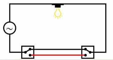
I was installing a new two way switch on a hallway light, the type with a switch at each end of the hallway (see diagram below). I decided to play it safe and use my multimeter to verify the open/closed position of the switches.
With the switch in the OFF position everything checked out, but with the switch in the ON position I found that there was a reading of 42 volts on what was supposed to be the "dead conductor" i.e. the red conductor in the diagram below.
I subsequently found articles on the web which verified that in this particular situation it is common for one of the conductors in standard household power cable to register an "induced voltage".
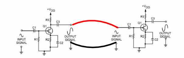
In the case of “conventional” power cable architectures, the live conductor and the neutral conductor tend to be side by side in extremely close proximity for the length of the cable, so is it reasonable to assume that noise will be induced between the conductors in a power cable?.
Would “noise pollution” also be present on the ground conductor, which, and depending on the design of a components circuit, might also have an adverse effect on sound quality?
Additional research revealed even more to consider regarding good cable design...
For more information on cable design issues please read the three articles below that talk about the many problems that challenge cables designers.
They will provide a great deal of insight into the many parameters and design techniques employed to build cables that excellent in their performance.
The articles are specific to Interconnect and speaker cables, but much of the theory also applies to power cables
https://www.psaudio.com/article/cables-time-is-of-the-essence-part-1/
https://www.psaudio.com/article/cables-time-is-of-the-essence-part-2/
https://www.psaudio.com/article/cables-time-is-of-the-essence-part-3/
The premise of the helical design concept eliminates the parallel conductors which minimizes cable issues to imperceivable levels!
But First My Disclaimer:
DO NOT attempt any of the assemblies detailed below unless you are an experienced Electrical Professional OR Electronics Hobbyist - otherwise consult a technician!
YOU ARE RESPONSIBLE: for following local electrical codes. Failure to do so may result in personal injury, damage to equipment, or power cable failure which can result in fire.
YOU ARE RESPONSIBLE: for ensuring the cable selected is suitably rated for the power requirements of the component(s) it will be attached too !
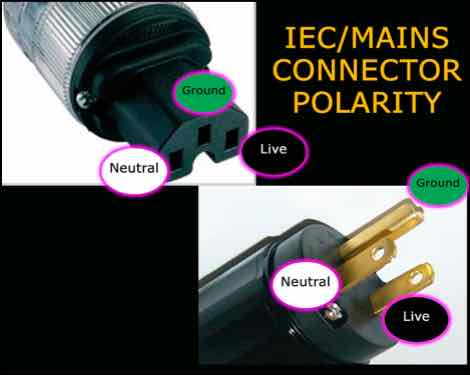
YOU ARE RESPONSIBLE: for ensuring the IEC/Mains connectors are installed observing the correct polarity !
- failure to do so can result in poor operation, component failure or electric shock.
YOU ARE RESPONSIBLE: for ensuring the dielectric strength of the insulation on ALL conductors used, meets or exceeds local codes!
e.g. In North America - 600v at 200 Celsius for 120v 50/60 Hz supply
These Power cables are only to be used for Home Audio Purposes and must not subjected to harsh environments and frequent handling, which generally require additional protective coverings.
The materials mentioned below comply with most codes for NORTH AMERICA ONLY!
Electrical codes in other countries may require the selection of different materials, therefore YOU ARE RESPONSIBLE for following those local electrical codes.
YOU are responsible for ensuring “power related” assemblies are safe to use!
Materials...
The materials listed below will build a 5ft power cable that is suitable for use with Power Aimplifiers rated up to 600 watts.
- LIVE Conductor: Duelund stranded 12 gauge wire with Polycast insulation
- However, if you want a more budget oriented power cable you can use 12 gauge Mil-spec wire from Take Five audio
- NEUTRAL Conductor: 30 feet of stranded Mil Spec 12 AWG Silver Plated Copper Wire, Cryo Treated, Red - available from Take Five Audio (TFA)
- GROUND Conductor: 15 feet of green 12 gauge mains copper wire from Home Depot
- 2 feet of 1” black Heat Shrink sleeve
- 1 Pair of SONAR QUEST CRYO Ag Audio Grade Silver plated IEC plug + US main plug
- lead free solder suited for electronics use - or WBT 4% silver solder can also be used
- 10-12 gauge copper spade/fork connectors
- For Spade/Fork terminals take look at the Grainger Web site and in their options check box select TERMINAL TYPE: Standard, WIRE RANGE: 12-10 gauge, INSULATION TYPE: Bare and SEAM: Butted
- Fork Terminals - Spade Terminals - Grainger Industrial Supply
- 1 5ft x 1/4” fibreglass rod - available from Home Depot
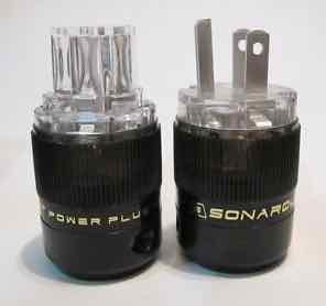
The Sonar Quest connectors have heavy Silver plating on pure copper contacts that provide excellent clamping and transmission of electrical current - available from ebay
I use an approximate ratio of 3:1 of Ground/Neutral:Live conductor
e.g. for a 5ft power cable I use 15ft of Ground and 30ft of Neutral Conductor
How To Make Them...
To determine the “Direction” of the Helix - see Inside The Helix Geometry.
The Neutral Conductor...
The Neutral Conductor is made from two lengths of the Mil Spec 12 AWG Silver Plated Copper Wire listed above.
Why two pieces? - this effectively make the neutral wire a 9 awg conductor, which I have found performs much better, resulting in faster dynamics, better bass performance and control and more natural imaging.
Cut the 30 ft length of wire into two equal length pieces.
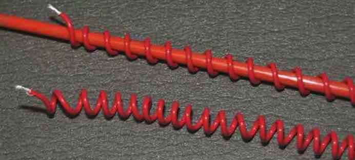
On the 1/4” rod, wind the neutral conductor in a helix configuration, space the windings about 1/4” apart and remove from the rod.
Repeat the winding process with the second piece of wire.
With the second coil of wire still on the rod...
- Attach the first coil to the second coil with a 10 gauge spade connector
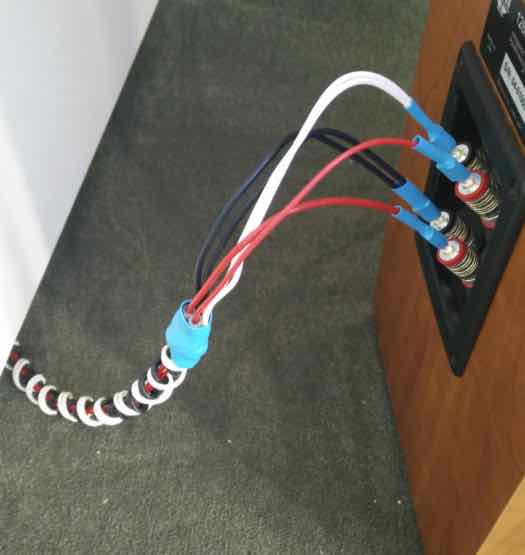
- Wind the first “coil” of wire between its windings as shown below
Remove the two “intertwined” coils from the rod
The Ground Conductor...
On the 1/4” rod, wind the green GOUND conductor in a helix configuration, space the windings about 1/4” apart and remove from the rod.
Attach a 10 awg spade connector on one end of the Live conductor, crimp and solder in place.
Thread the Live conductor through the centre of the red coil(s)
Attach a second 10 awg spade connector on free end of the Live conductor, crimp and solder in place.
Attach a second 10 awg spade connector on the two free ends of the neutral conductor, crimp and solder in place.
Wind the green wire between the “double winding” of the neutral conductor as shown below.
Place 12 awg spade connectors on both ends of the ground conductor, crimp and solder in place
Place the expandable nylon sleeve over the cable assembly and cut to length
- NOTE: I no longer use the Nylon sleeve because I like the look of the green/red conductors
Cut two adequate lengths of 1” heat shrink tubing and place over the nylon sleeve
Attach the Sonar Quest connectors to the cable assembly ensuring you adopt the correct polarity!!!
Position the heat shrink over the ends of the outer sleeve and apply heat
Secure the connector covers in place to complete the cable assembly
Assembly Notes...
Why do I use spade connectors? -
- First, trying to attach the mains/IEC connectors to a 10 gauge cable is very difficult,
- More importantly - the spade connectors prevent detachment from the connectors in the event of unforeseen stress being placed on the connectors.
- I have also found that the spade connectors actually improve sound quality.
For a more secure crimped joint, I always crimp from the back - as shown in the image below, which prevents the collar from opening.
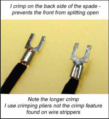
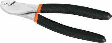
I use pliers as shown in this image that applies an extended crimp along the whole length of the spade connectors collar
Cables that are more suited to source components can use lighter gauge conductors, but be sure to determine their power requirements and select a gauge that can handle it with headroom to spare.
Can you use other brands of IEC/Mains connectors?
Of course. Some people might prefer to use Furutech, or Oyaide high quality connectors.
Others may prefer to use something more reasonably price, like the Vanguard range of connectors.
I believe the Sonar Quest connector line provides exceptional sound quality for a reasonable price.
The Journey...
I’m a frugal person with a distinct dislike of overpaying for something as simple as a piece of wire!
I started making my own cables many years ago from Bulk cable with reasonably priced connectors.
I first tried Furutech bulk cable and then stumbled upon DH Labs, which I believe offers similar performance for about 1/3 the price - how could you not like that.
I then investigated a braided architecture which proved very effective, even using plain old Romex house wire.
Finally, I tried the Helix Architecture, which has proved to be the best performing power cable architecture to date.
I have now implemented this architecture on all my cables that have anything to do with audio.
What do they sound like?
The “POWER HELIX” is a high performance power cable that allows connected components to perform to the best of their abilities.
They assist components in delivering ultra fast dynamic performance, exceptional clarity, expansive imaging and a very deep and exceptionally well controlled bass performance with improved imaging.
How Long is the Burn-In Period?
It is imperative that these cables are allowed adequate time to settle and burn-in...
- they will sound extremely good on initial installation
- after about 60 hours they allow more of the micro details in the form of venue specific reverberation captured in live recordings, or applied by very talented sound engineers, to clearly be heard.
The end of the Road?
I have decided to end this particular power cable “obsession” with the “POWER HELIX” simply because...
- the cost of better materials is making them significantly more expensive
- I believe any improvements using better materials will probably be marginal from this point onwards
My hope is that this design will be embraced and enhanced by the DIY Community and encourage them to experiment with different conductor materials and configurations to tailor the sound to their own liking.
For Helix cable spec’s please see Its More Than Just Numbers - Isn't It?
My Review System:
Custom built turntable with a Soundsmith Denon DL103 phono cartridge mounted on an Audiomods Arm with one piece silver litz harness + KLEI Absolute®Harmony RCA’s
Simaudio MOON LP5.3 RS phono stage
Bluesound Node 2 music server
NAIM 5i integrated amp (with passive pre-section).
Gershman Acoustics Sonogram speakers.
KLE Innovations gZero6 Speaker Cables
 Give them a try - and - Enjoy The Music!
 ![]()
DIY Interconnect Cables - The "Helix Mark VIII"
Now includes a Balanced design...
The “Helix Mark VIII” represents the very latest developments in researching different wire types and materials. The only difference is that the Mark VII uses Duelund wire for the signal conductor and the Mark VIII uses Mundorf Solid Silver/gold (see below for details)
The premise behind its helical geometry (or architecture) is eliminating parallel conductors, since...
- if two parallel conductors are in close proximity for an extended distance, and current is passed down them, then noise & distortions will occur within them them.
Why would this matter? Isn’t the neutral is effectively connected to the “ground” ?
Well, the neutral conductor is actually connected to the neutral side of the circuit of both attached components.
Any noise permeates through the neutral side of the components circuit, which has a negative impact on the amplified signal resulting in a distorted output.
Any noise in the signal conductor gets amplified and distorted even further
In addition, parallel conductors are prone to Proximity & Skin Effects which alters the resistance of the conductor. affecting the transfer the signal
All of this impacts the phase between the left and right channels, which “smears” the mage.
The helix design concept eliminates the parallel conductors and minimizes the noise, proximity effect and Skin effect to imperceivable levels, improving clarity and dynamic performance of the interconnect.
One other nice feature of the helical design is the neutral conductor, being wound around the signal conductor, becomes a very effective shield against external RFI sources - because it is connected to “ground” ![]()
But Shouldn’t The Two Conductors Be The Same Length?
If you look at the “roles” the two conductors play from the perspective of an attached components’ circuit diagram it becomes clear that cable length is immaterial and they can be made from different materials and gauges.
- The Signal Conductor transfers the signal
- The Neutral Conductor completes the circuit, however, it also connects the neutral sides of the two attached components
- Any “noise” present on the neutral conductor impacts the operation of BOTH components.
For more detailed information on cable design issues please read the three articles below that talk about the many problems that challenge cables builders.
They will provide a great deal of insight into the many parameters and design techniques employed to build cables that excellent in their performance.
https://www.psaudio.com/article/cables-time-is-of-the-essence-part-1/
https://www.psaudio.com/article/cables-time-is-of-the-essence-part-2/
https://www.psaudio.com/article/cables-time-is-of-the-essence-part-3/
How To Make Them...
To determine the “Direction” of the Helix - see Inside The Helix Geometry.
The Single Ended IC Design...
The parts list is reasonably priced between $180 - $250 CDN for a 3ft ( or 1 meter) pair, depending on the RCA’s selected - and all other parts can be purchased from many parts providers on the web.
Considering their exceptional sound quality I believe this price range to be excellent value.
You can upgrade or downgrade these parts if you wish, but the parts listed will provide exceptional sound quality.
I use an approximate ratio of 3:1 of Neutral:Signal conductor
e.g. for a 3ft Interconnect cable I use 9ft of Neutral Conductor
The quantities listed is for a single Interconnect cable i.e. one channel - so double them for a stereo pair
- RCA Plug: KLE Innovations Absolute Harmony RCA Plugs (SOURCE: KLE Innovations or local parts sources)
- Neutral Conductor: 9 ft of Mil Spec 16 AWG Silver Plated Copper Wire Green Cryo Treated (SOURCE: TAKE FIVE AUDIO - TFA)
- Signal Conductor: 3 ft of 20 gauge Duelund stranded Tinned Copper with Oil/Cotton insulation (Source: HiFi Collective). See NOTE A below
- Teflon Tube: 3 ft of PTFE 10 Tubing .106"ID .130"OD Approx. (SOURCE: TFA)
- WBT 4% silver solder
NOTE A: The Signal Conductor
- I have listed the Duelund wire as the signal conductor, but I have found 20 gauge Mundorf Silver/gold solid wire without insulation provides even more details and a stunning image. However, the Mundorf wire is significantly more expensive than the Duelund wire.
Step 1.
I first wind the conductor around a 5mm metal rod. To assist with this I insert the rod into a variable speed hand drill and feed the conductor along its length.
Once wound, the helix can be removed from the dowel.
Step 2
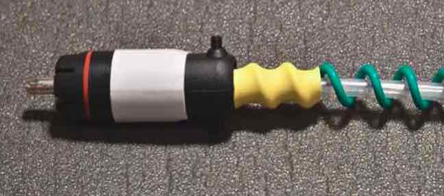
Insert the teflon tube into the helix.
Space the windings over the length of the tube
Tighten the helix by twisting it, about an inch at time, along the length of the cable
Secure with a small piece of heat shrink or electrical tape
Step 3
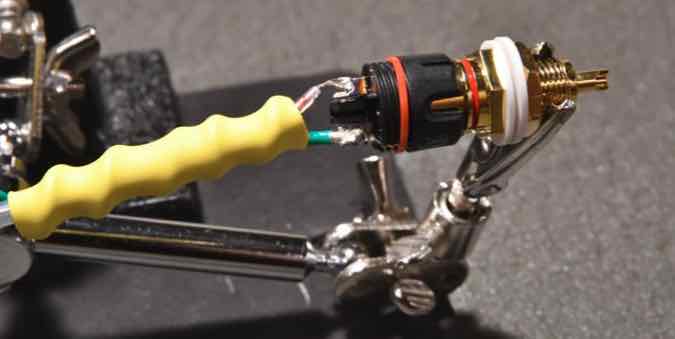
Soldering the KLE Innovations needs a little care to prevent excess heat from damaging the plastic housing
I use a chassis mount RCA jack and insert the RCA base into it in order to wick away excess heat
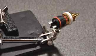
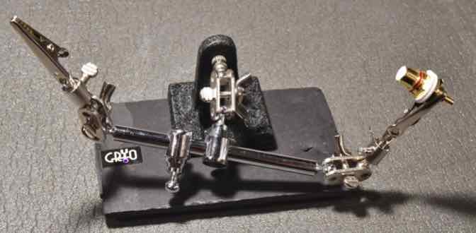
I also use a little “rig” to hold the parts while I solder
I’ve found that it is easier if I first solder the signal wire to the RCA plug first, followed by the neutral wire
Install the housing of the RCA and tighten the screws
To finish off, you can add some expandable nylon sleeve - it does not impact the performance of the Interconnect.
Assembly Notes...
For the budget minded DIYer I have since found that 24 gauge silver plated Mil-Spec wire offers a fuller sound without sacrificing any details and reduced the cost of the cable significantly. I also use it for the neutral.
But for the best performance to date, I now recommend either Mundorf 20 gauge copper wire with oil/cotton insulation or bare Mundorf Solid Silver/Gold(1%) wire.
- Dueund is marginally more expensive than the Mil-Spec wire and is a great performer
- But the Mundorf wire provides the most details and the best imaging,
- They really open up the image and presents a fuller, more detailed image with superb dynamics.
- I only use these wires for for the signal conductor
- I tried the Duelund as the neutral and it did not sound any better than the Mil-spec wire
- I continue to use the Mil-spec wire for the neutral.
I leave it up to you as to which wire you select, but all the wires mentioned above will outperform most of the commercial products currently available
Can you use other brands of RCA?
NOT RECOMMENDED!
I recommend KLE Innovations Harmony RCA’s because of their stellar performance. Personally, I use the Absolute Harmony RCA because it is their best performer.
The properties of the KLEI Harmony RCA’s are very different from conventional RCA’s, such that they can be used on single ended SPDIF cables without experiencing the issues associated with conventional RCA’s not rated at the same impedance as the cable because their impedance exceeds 110 ohms.
e.g. “convention” states that a SPDIF cable should use an RCA plug of identical impedance
Primarily to reduce/eliminate internal “reflections” of the digital signal back down the cable
However, the KLEI Harmony RCA’S can be used on most digital cables regardless of the cables rated impedance value.
I also believe their higher impedance is responsible for their stellar analogue performance.
Can this cable be used for SPDIF purposes?
Absolutely! - it is an extremely adept SPDIF cable!
And I have found that the following cost saving adjustments do not impact SPDIF performance at all...
- KLEI Silver Harmony RCA plugs can be used in place of the more expensive Absolute Harmony RCA plug
- The Silver plated Mi-Spec wire is used for the signal conductor
To date, it is the best SPDIF cable I have used.
What do Helix Mark VIII sound like?
The “Helix Mark VIII” is a very high performance interconnect cable with extremely high resolution capabilities.
They deliver a completely “uncoloured presentation” with ultra fast dynamic performance, exceptional clarity, expansive imaging and a very deep and exceptionally well controlled bass performance.
They excel in the delivery of one of the most realistic presentations of live recordings I have observed.
- The delicate nuances pertaining to the acoustic reverberations of instruments and voice within a live venue are faithfully reproduced in the most minute detail, with a precision placement of musicians and their instruments within their own “virtual space”.
My system components are quite modest by today’s standards. However my cables are all excellent performers and they work in harmony with the components to achieve an excellent overall “system performance”.
Will the “Helix Mark VIII” perform well on all systems?
Based on feedback from people who have made them for some quite varied systems, I have no reason to believe their performance will be anything less than stellar.
The Balanced (XLR) IC Design
The quantities listed is for a single Interconnect cable i.e. one channel - so double them for a stereo pair
- 2 pairs of Neutrik NC3FXX-HA Male/Female XLR Cryo Treated - with Silver Plated Pins ( SOURCE: TAKE FIVE AUDIO - TFA)
- Neutral Conductor: 9 ft of Mil Spec 16 AWG Silver Plated Copper Wire Green Cryo Treated (SOURCE: TAKE FIVE AUDIO - TFA)
- Signal Conductor: 6 ft oof 20 gauge Duelund stranded Tinned Copper with Oil/Cotton insulation (Source: HiFi Collective)
- Outer Teflon Tube: 6 ft of PTFE 10 Tubing .106"ID .130"OD Approx. (SOURCE: TFA)
- WBT 4% silver solder
The Balanced XLR IC design is “basically” the same as single ended design with simple modification.
A balanced cable requires two signal conductors
- one for the positive signal
- one for the negative signal
- Insert the signal conductors in a piece of teflon tube
- gently twist the teflon tubes together - 0ne twist every 5-6 inches
As with the single ended design, wind the neutral conductor in a tight spiral around a dowel
Stretch the spiral a little and then wind the neutral around both the signal conductors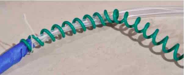
Add the plugs and VOILA!
Nylon Expansion sleeve can be applied to get the “professional look” if desired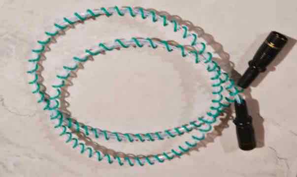
Below is a photo of a completed pair - built by a fellow DIY Audiophile John Tupper - thanks John ![]()
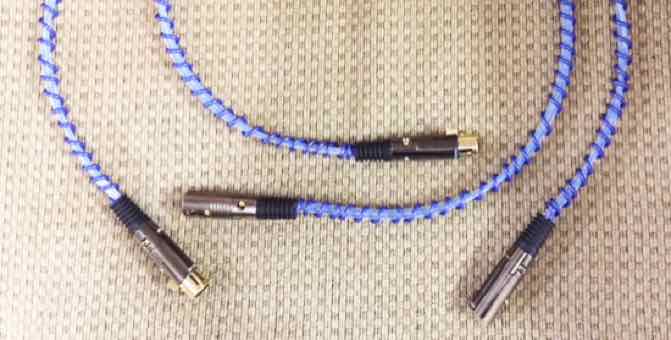
A quote from John,,,
- “My system is now running four of your power cables, XLR interconnects and speaker cables. More burn-in likely required, but, with 72 hours of running they sound fantastic.”
The Journey...
I’m a frugal person with a distinct dislike of overpaying for something as simple as a piece of wire!
I started making my own cables many years ago, but many of those utilized bulk cable from companies like Van den Hul and DH Labs.
I then investigated some of the more recent cable geometries such as tight twisted pairs, braiding and helix geometries.
My biggest issue with helix designs as a DIYer - how to maintain a uniform distance between the signal and neutral conductors - the teflon tubes alleviated this problem
My primary goal along the way was to keep the cost of materials to a minimum.
When I first tried the early CAT6 version of the Helix design it was quite clear that it was going to be a very adept performer.
This observation supported my belief that the Helix architecture (or geometry) was an extremely effective approach to achieving excellent cable performance.
The early versions utilizing CAT6 as the neutral conductor were very good - just not brilliant!
With the “Helix Mark VII” version, I decided to incorporate higher quality silver plated materials in the neutral conductor in the hope that I could come even closer to the performance levels of some of todays popular high performance cables for a fraction of the cost.
The improvements were so good I concluded that a larger gauge neutral conductor provides significant improvements and the Duelund signal conductors were the icing on the cake - and Voila...
the “Helix Mark VII” was born!
The result:
a cable that actually competes with some of the very best cables in the audio world!
C’mon, Really?
- OK, I’ll let you be the final judge, but after listening to many cables I believe this to be the case

How Long is the Burn-In Period?
It is imperative that these cables are allowed adequate time to settle and burn-in, which is typically >300 hours.
- they will however sound extremely good on initial installation
- they may exhibit some loss in volume and image focus after 3-4 days continuous use, but will return to normal by day 6-7
- they will sound exceptional after around 200 hours, but they will get even better after 300 hours
- I have also found ongoing improvements occur up to approximately 600+ hours in the earlier versions
- The use of cable cookers will expedite this process - start with 100 hours cooking + 100 hours playing
The end of the Road?
I have decided to end this particular interconnect cable “obsession” with the “Helix Mark VIII” simply because...
- the cost of better materials is making them significantly more expensive
- the improvements using better materials will probably be marginal from this point onwards
My hope is that this design will be embraced and enhanced by the DIY Community and encourage them to experiment with different conductor materials to tailor the sound to their own liking.
- Since the original posting back in 2015, I have exchanged email with several fellow Diyer’s that have contributed to the Helix design.
- Some people that have contributed to the evolution of the Mark VII design, including: Ernst (Austria), Yordan (Bulgaria), Ghislain (Canada), Todd (USA), John (USA)
For Helix cable spec’s please see Its More Than Just Numbers - Isn't It?
My Review System:
Custom built turntable with a Soundsmith Denon DL103 phono cartridge mounted on an Audiomods Arm with one piece silver litz harness + KLEI Absolute®Harmony RCA’s
Simaudio MOON LP5.3 RS phono stage
Bluesound Node 2 music server
NAIM 5i integrated amp (with passive pre-section).
Gershman Acoustics Sonogram speakers.
KLE Innovations gZero6 Speaker Cables
Assorted power cables
 Give them a try - and - Enjoy The Music!
 ![]()
ADDENDUM:
Audiogon Member Toddverrone has also tried these IC’s ...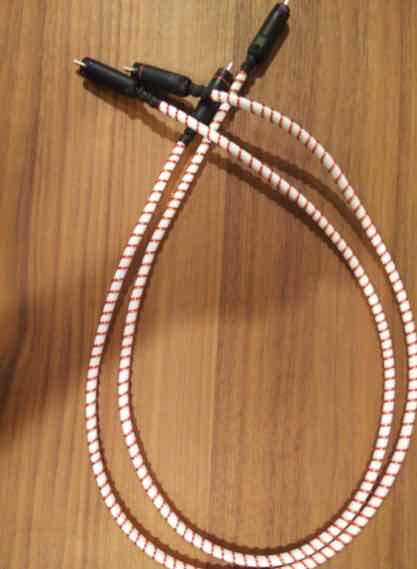
The Parts List :
- signal wire: OCC solid silver 24awg in cotton. 3' per cable
- neutral: OCC solid copper 20awg magnet wire. 2 x 9' per cable
- connectors: KLE pure harmony solid silver
- the white tube is a foamed teflon flexible tube that i ran the signal through. it's pretty amazing. it doesn't kink at all. it's called hyperflex tubing from vh audio
Todd’s Feedback...
I’m still listening to them, but initial findings on the helix ICs are incredibly positive.
More of the helix magic: less noise, greater clarity, better separation of sound sources.
Good stuff!