


cables
The HELIX USB Cable
01/01/19 10:02 *HELIX USB Cable*HELIX IMAGE USB Cable
This post details how to fabricate a USB cable using the Helix cable geometry and is provided by courtesy of Audiogon Member : Grannyring.
Please Note: this cable does not include the conductor that carry USB supplied power.
The fabrication of this cable follows the same approach used in the construction of the analogue interconnects and has…
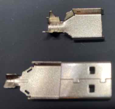
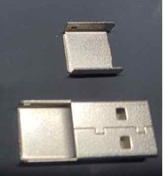
Unfortunately, the TYPE A and TYPE B connectors used are really designed for 24/28 gauge wires and definitely NOT designed for use with the Helix Coil, i.e. without a simple modification
Simply remove the Cable clamps as in the diagrams below
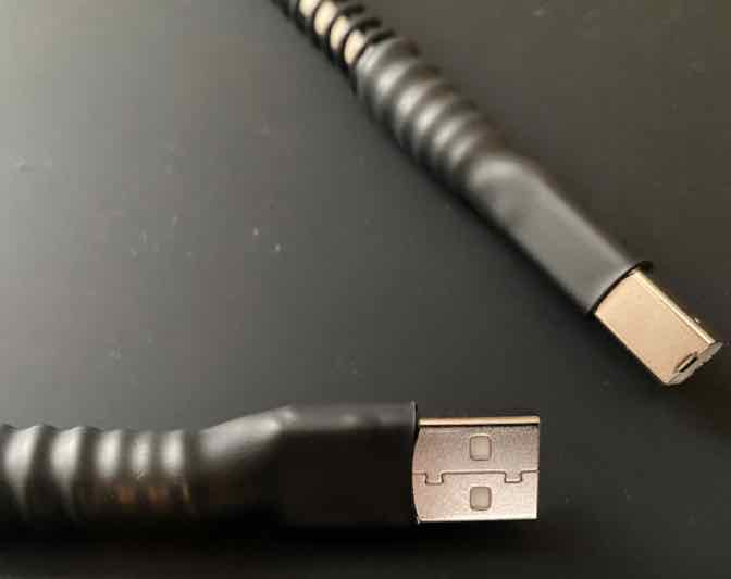
TYPE A USB CONNECTOR
BEFORE AFTER
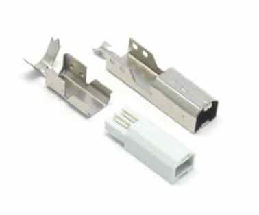
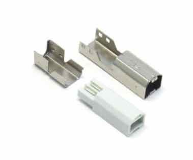
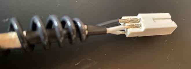
TYPE B USB CONNECTOR
BEFORE AFTER
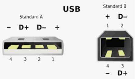
NOTE: When attaching the wires please ensure you observe the correct pin connections
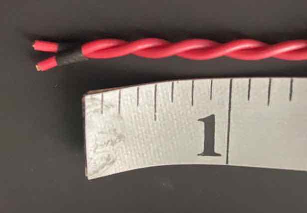
Next, construct the D+ and D- Twisted Pair using a "short twist" as in the image below
You can use the same 18 gauge wire as used with the Analogue Interconnect, but since there is very little space in the USB connectors the problem of wires shorting out requires extremely precise soldering
The recommended wires for this cable is:
Please note that either of the signal wires above will perform to a very high level, but for the very best performance, the solid silver wire is preferred
Insert the twisted pair into a piece of cotton tubing with heat-shrink (with adhesive) at each end to hold it in place
Insert that assembly into the Helix Coil and attach the connectors…
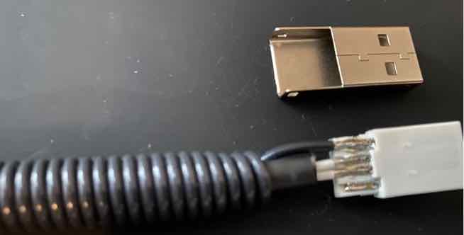
Connect one end to the Type A connector.
Stretch the Helix coil to the length of the signal wires
Connect the other end to the Type B connector.
Here is a view of the wires connected to the top of the Type B connector
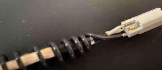
And a view of the wires connected to the Bottom of the Type B connector
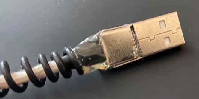
Once the wires are soldered in place, Fix the metal housing in place using a hot glue gun.
Be sure to cover the solder joints with hot glue, so as to insulate them from the metal housing
Hot glue the metal cap into place, again covering any solder joints with the glue.
NOTE: Add a little more hot glue to secure the cable assembly to the connector, for strain relief
Do this for both Type A and Type B Connectors
Place two pieces of Heat-shrink (with adhesive) over each connector assembly and the Helix coil to provide additional "strain relief"
NOTE: ensure the Heat Shrink extends onto the Helix Coil by approximately 1.5 inches.
- This prevents the cable from bending and breaking the the delicate solder joints.
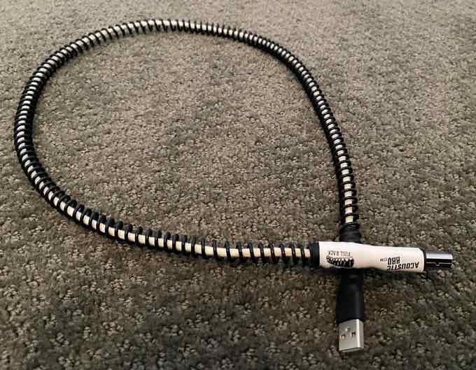
And VOILA ! - you have a high performance USB cable
PLEASE NOTE: Before connecting any cable to a component be sure to test the continuity of the pins of each connector
How do I add the Power Supply Wires?
If you would like to add the wire that will provide USB power to the connected device as follows…
Audiogon member Grannyring has reported that the Solid Silver conductor from VH Audio provided the highest quality he has ever heard from his USB DAC.
Please Note: this cable does not include the conductor that carry USB supplied power.
- adding a separate cable for this purpose is detailed below
The fabrication of this cable follows the same approach used in the construction of the analogue interconnects and has…
- A twisted pair that carries the D+ and D- digital signals
- NOTE: using the D+ and D- is a differential signalling technique as used in XLR "Balanced" cables.
- A Helix Neutral conductor that is connected to the neutral side of the circuit
Unfortunately, the TYPE A and TYPE B connectors used are really designed for 24/28 gauge wires and definitely NOT designed for use with the Helix Coil, i.e. without a simple modification
Simply remove the Cable clamps as in the diagrams below
TYPE A USB CONNECTOR
BEFORE AFTER
TYPE B USB CONNECTOR
BEFORE AFTER
NOTE: When attaching the wires please ensure you observe the correct pin connections
Next, construct the D+ and D- Twisted Pair using a "short twist" as in the image below
- i.e. 3 twists per inch (or per 25mm)
You can use the same 18 gauge wire as used with the Analogue Interconnect, but since there is very little space in the USB connectors the problem of wires shorting out requires extremely precise soldering
The recommended wires for this cable is:
- 18 gauge UP-OCC Solid Silver with AirLok insulation from VH Audio for the signal wire, or
- 18 gauge UP-OCC Solid Copper with AirLok insulation from VH Audio
- 16 gauge Silver Plated Mil-spec for the Helix Neutral (i.e. as used on the Analogue Interconnects)
Please note that either of the signal wires above will perform to a very high level, but for the very best performance, the solid silver wire is preferred
Insert the twisted pair into a piece of cotton tubing with heat-shrink (with adhesive) at each end to hold it in place
Insert that assembly into the Helix Coil and attach the connectors…
Connect one end to the Type A connector.
Stretch the Helix coil to the length of the signal wires
Connect the other end to the Type B connector.
Here is a view of the wires connected to the top of the Type B connector
And a view of the wires connected to the Bottom of the Type B connector
Once the wires are soldered in place, Fix the metal housing in place using a hot glue gun.
Be sure to cover the solder joints with hot glue, so as to insulate them from the metal housing
Hot glue the metal cap into place, again covering any solder joints with the glue.
NOTE: Add a little more hot glue to secure the cable assembly to the connector, for strain relief
Do this for both Type A and Type B Connectors
Place two pieces of Heat-shrink (with adhesive) over each connector assembly and the Helix coil to provide additional "strain relief"
NOTE: ensure the Heat Shrink extends onto the Helix Coil by approximately 1.5 inches.
- This prevents the cable from bending and breaking the the delicate solder joints.
And VOILA ! - you have a high performance USB cable
PLEASE NOTE: Before connecting any cable to a component be sure to test the continuity of the pins of each connector
How do I add the Power Supply Wires?
If you would like to add the wire that will provide USB power to the connected device as follows…
- Once the USB connectors have been soldered to the D+ and D- twisted pair BUT before the hot glue has been applied to the connectors
- Cut a length of 18 gauge wire slightly longer than the length of the USB cable
- insert the wire into a piece of braided screen tube (approximately 1" shorter than the piece of wire)
- Then insert the wire and the braided shield into a piece of expandable nylon sleeve (for insulation) and secure with a piece of heat shrink at both ends
- PLEASE NOTE: - the screen is NOT connected to either of the USB connectors
- connect one end of the power wire to the +ve power pin of one connector
- "loosely twist" the power wire assembly around the Helix coil ( i.e. about 4 times around for a 3 ft cable) - this keeps the +ve wire close to the cable
- solder the other end of the +ve wire to the other USB connector
- hot glue the metal casings onto the USB onnectors as detailed above
- Add the two pieces of heat-shrink (with adhesive) over the connector, helix coil and the +ve wire with screen (as shown above)
Audiogon member Grannyring has reported that the Solid Silver conductor from VH Audio provided the highest quality he has ever heard from his USB DAC.