


The "HELIX IMAGE" Interconnect
The premise behind its helical geometry (or architecture) is eliminating parallel conductors, since...
- if two parallel conductors are in close proximity for an extended distance, and current is passed down them, then noise & distortions will occur within them.
Why would this matter? Isn’t the neutral is effectively connected to the “ground” ?
Well, the neutral conductor is actually connected to the neutral side of the circuit of both attached components.
Any noise that permeates through the neutral side of the components circuit, will have a negative impact on the connected components, resulting in distortions in the signal, which is ultimately amplified and output to the speakers.
Any noise in the signal conductor gets gets distorted even further through each stage and again amplified even further
In addition, parallel conductors are prone to Proximity & capacitance issues which creates distortions in the conductors.
All of this impacts the phase between the left and right channels, which “smears” the mage.
The original helix design concept eliminates the parallel conductors and minimizes the noise to imperceivable levels, improving clarity and dynamic performance of the interconnect.
Since those early days, developments include the selection of various types of wire, gauge of wire and types of insulation, to bring us to this moment in time
One other nice feature of the helical design is the neutral conductor, being wound around the signal conductor, becomes a very effective shield against external RFI sources - in effect is is a Faraday Cage surrounding the signal wire - because it is connected to “ground” ![]()
But Shouldn’t The Two Conductors Be The Same Length?
If you look at the “roles” the two conductors play from the perspective of an attached components’ circuit diagram it becomes clear that cable length is immaterial and they can be made from different materials and gauges.
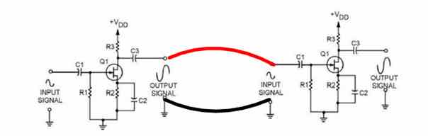
- The Signal Conductor transfers the signal
- The Neutral Conductor completes the circuit, BUT, its ONLY function is to connect the neutral sides of the two attached components
- Any “noise” present on the neutral conductor permeated through the entire circuit of BOTH components and impacts their operation.
For more detailed information on cable design issues please read the three articles below that talk about the many problems that challenge cables builders.
They will provide a great deal of insight into the many parameters and design techniques employed to build cables that excellent in their performance.
https://www.psaudio.com/article/cables-time-is-of-the-essence-part-1/
https://www.psaudio.com/article/cables-time-is-of-the-essence-part-2/
https://www.psaudio.com/article/cables-time-is-of-the-essence-part-3/
How To Make Them...
FIRST: determine the “Direction” of the Helix for the wire you will use - see Inside The Helix Geometry.
The Single Ended IC Design...
The parts list is reasonably priced between $180 - $250 for a 3ft ( or 1 meter) pair, depending on the RCA’s and wire selected - and all other parts can be purchased from many parts providers on the web.
Granted, they are more expensive than most other DIY cables, but considering their exceptional sound quality and their ability to compete with many top of the line cables from established commercial brands, I believe this price range to be of excellent "value".
You can upgrade or downgrade these parts if you wish, but the parts listed will provide exceptional sound quality.
I use an approximate ratio of 3:1 of Neutral:Signal conductor
e.g. for a 3ft Interconnect cable I use 9ft of Neutral Conductor
The quantities listed is for a single Interconnect cable i.e. one channel - so double them for a stereo pair
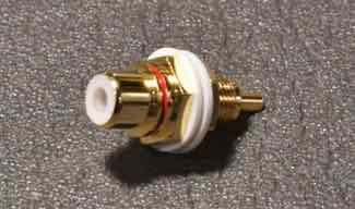
- RCA Plug: KLE Innovations Absolute Harmony RCA Plugs (SOURCE: KLE Innovations or local parts sources)
- Neutral Conductor: 9 ft of 16 gauge solid Neotech UP-OCC Solid Copper wire with Teflon insulation
- Signal Conductor: 2 x 3 ft of 18 gauge bare UP-OCC Solid Copper wire - My preference, with the Teflon insulation removed.
- OR: for a slightly more mellow presentation use 2 x 18 gauge UP-OCC solid copper with AirLok insulation from VH Audio
- OR: 2 x 18 gauge UP-OCC solid Silver wire with AirLok insulation from VH Audio for a very detailed and smooth performance
- WBT 4% silver solder OR Cardas Eutectic solder
Assembly of the “HELIX IMAGE DOUBLE/SINGLE” interconnect...
i.e. the Live conductor has two wires and he neutral conductor is a single wire
Step 1.
Construct the Signal conductor as indicated in The HELIX IMAGE (Air)
Step 2.
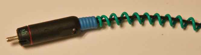
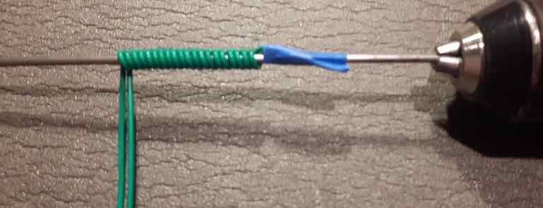
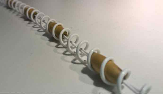
Wind the conductor around a 3/16" (5mm) metal rod. To assist with this I insert the rod into a variable speed hand drill and feed the conductor along its length.
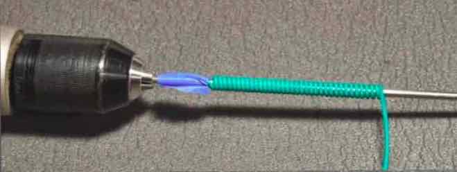
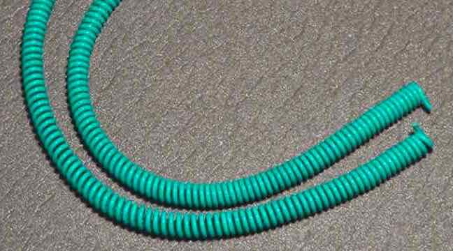
Once wound, the helix can be removed from the rod.
Step 3
Insert the signal wire into the helix.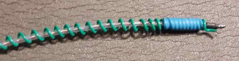
Space the windings over the length of the signal wire
You may need to tighten the helix by twisting it, about an inch at time, at each end to accommodate the RCA housing
Place a small piece of Heat shrink tube at the end to allow the two small set screws in the housing to grip the cable.
Step 4
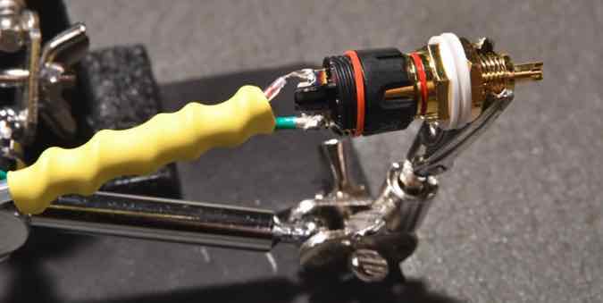
Soldering the KLE Innovations needs a little care to prevent excess heat from damaging the plastic housing
I use a chassis mount RCA jack and insert the RCA base into it in order to wick away excess heat
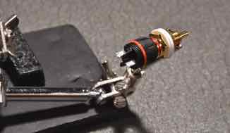
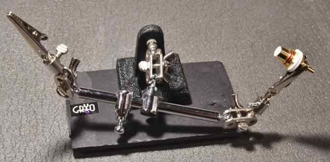
I also use a little “rig” to hold the parts while I solder
I’ve found that it is easier if I first solder the signal wire to the RCA plug first, followed by the neutral wire
Install the housing of the RCA and tighten the screws and you are done!
Assembly of the “HELIX IMAGE DOUBLE/DOUBLE” interconnect...
This is the adaption that Bill (a.k.a. Grannyring on the Audiogon Forum) made me aware of. It was adapted from an approach known in audio circles as the "Schroeder Method" and Bill's adaption basically doubled up on both the Signal wire and the neutral wire of the Helix coil.
The construction approach is identical to the single wire IC above with the following changes…
THE SIGNAL CONDUCTOR:
Is identical to the signal conductor used in the DOUBLE/SINGLE cable above
THE NEUTRAL CONDUCTOR:
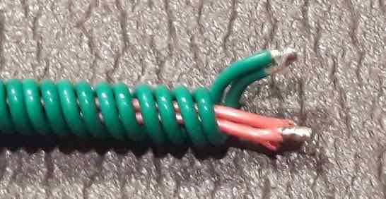
To make the Double helix coil, strip about 3/8" (10mm) of insulation from the ends of two lengths of 16 gauge Neotech wire (with Teflon insulation) , twist tightly and solder
Then carefully form the coil using a variable speed drill by winding both wires.
Insert the Signal wire into the helix coil
Then just as with the single wire version
- Stretch the coil out to the length of the signal wire
- Place a piece of heat shrink on the end of the cable
- attach the RCA plugs
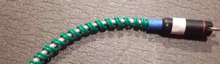
Please note: in the picture above I have used Cotton insulation - which is a personal preference.
Assembly of the “HELIX IMAGE DOUBLE/SINGLE” interconnect...
So WHY all the different versions?
Well, I was pretty happy with the Single wired version, but Bill had reported significant improvement using the Double/Double approach.
My first thought was that I would just double-up the signal wire to see what kind of improvement I might achieve and leave the Helix Coil as a single wire
The results were very compelling and significantly better than the single wired version.
So now I had to try the Double/Double version in order to assess just how much better the Double/Double was than the Double/Single version.
CONCLUSION:
Well, the Double/Double is the best performer of the three, however, I found that the Double/Single provided about 65% of the benefit of the Double/Double.
What improved in both these cables over the single wired version as the precision and focus within the image, with a more realistic reproduction and a fuller sound
But the Double/Double just edged out the Double/Single version with a slightly improved presentation.
So, for those that already have the single wired version - upgrading to the Double/Single version is a very easy process with minimal cost and effort.
For those of you that is just trying the Helix for the first time and want to minimize the expense, the Single/Single is still an excellent cable and the upgrade to the Double/Single is very easy.
But once you've sampled the Helix IMAGE, you too may be tempted by the Double/Double
I now use a single wire of 16 gauge Neotech wire with Teflon insulation on both interconnects and it sound pretty amazing
Also, you might want to try different brands of wires for the signal conductor, e.g. some people prefer Mundorf Solid SIlver and others prefer Duelund tinned copper with Cotton Insulation - the choice is yours to make - there is no right or wrong
Can you use other brands of RCA?
NOT RECOMMENDED!
I recommend KLE Innovations Harmony RCA’s because of their stellar performance. Personally, I use the Absolute Harmony RCA because it is their best performer. I have used Furutech plugs, but the KLE Innovations product outperform the other RCA plugs I have tried, including Neotech Furutech and WBT RCA plugs.
Also, the properties of the KLEI Harmony RCA’s are very different from conventional RCA’s, such that they can be used on single ended SPDIF cables without experiencing the "reflection" issues associated with conventional RCA’s .
e.g. “convention” states that a SPDIF cable should use an RCA plug of identical impedance
Primarily to reduce/eliminate internal “reflections” of the digital signal back down the cable
However, the KLEI Harmony RCA’S can be used on most digital cables regardless of the cables rated impedance value.
I also believe their higher impedance is responsible for their stellar analogue performance.
Can this cable be used for SPDIF purposes?
Absolutely! - it is an extremely adept SPDIF cable!
To date, it is the best SPDIF cable I have used.
What do HELIX IMAGE Interconnects sound like?
The “HELIX IMAGE Interconnect” is a very highly resolving cable providing extremely good performance metrics with ultra-low distortion.
They deliver a completely “uncoloured presentation” with ultra fast dynamic performance, exceptional clarity, expansive imaging and a very deep and exceptionally well controlled bass performance.
They excel in the delivery of one of the most realistic and compelling presentations of live recordings I have observed.
- The delicate nuances pertaining to the acoustic reverberations of instruments and voice within a live venue are faithfully reproduced in the most minute detail, with a precision placement of musicians and their instruments within their own “virtual space”.
My system components are quite modest by today’s standards. However my cables are all excellent performers and they work in harmony with the components to achieve an excellent overall “system performance” that exceeds it’s price point by a considerable margin.
Will the “HELIX IMAGE Interconnect” perform well on all systems?
Based on feedback from people who have made them for installation in some quite varied systems, including all tube, tube hybrid and solid state, so I have no reason to believe their performance will be anything less than stellar on most systems.
However, each listener is unique and the synergy between components is varied, so you may need to adjust you particular cables to suite you YOUR ears. To that end I have provided the names of two wires that perform very well, but will allow you to personalize to your tastes.
Helix Geometry Adaptions…
The HELIX IMAGE Balanced (XLR) Interconnect
For a 3ft stereo pair:
- 2 pairs of Neutrik Male/Female XLR Cryo Treated - with Silver Plated Pins ( SOURCE: TAKE FIVE AUDIO - TFA)
- For even better performance these are available on eBay
- Hi-End Silver plated Tellurium Copper Male female XLR balance Connector
- Neutral Conductor: 18 ft of Mil Spec 16 AWG Silver Plated Copper Wire Green Cryo Treated (SOURCE: TAKE FIVE AUDIO - TFA)
- Signal Conductor: 12 ft of 20 gauge Duelund stranded Tinned Copper with Oil/Cotton insulation (Source: HiFi Collective)
- WBT 4% silver solder
The “standard” Balanced XLR IC design is “basically” the same as single ended design with a simple modification.
A balanced cable requires two signal conductors
- one for the positive signal
- one for the negative signal
- gently twist the signal wires together - 0ne twist every 5-6 inches
- Wind the neutral wire around a 6mm rod
- Insert the signal wires into the Helix
- add XLR connectors and Voila - you have a Helix XLR Interconnect cable
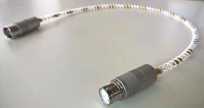
NEW DESIGN: The “HELIX IMAGE Mundorf (XLR)” Interconnect
Fellow DIYer, Yordan from Bulgaria, sent me this “upgrade” to the original XLR Interconnect design using wood beads similar in principle to the single ended design above, while incorporating Ernst’s approach of eliminating the use of man made sleeving/heatshrink and incorporating wood beads spaced along the signal conductor
The material choices, design elements and construction techniques of this cable makes it a worthy “HELIX IMAGE Mundorf” XLR Interconnect
if you wish to apply Yordan’s modifications and elevate your cable to the version shown below you will need ...
- Mundorf silver/gold wire, 0.5mm dia, SGW105 Teflon Insulated for the signal wire
- Mundorf silver/gold wire, 1mm dia, SGW110 Teflon Insulated for the neutral Helix
- 20 - 6mm diameter x 15 mm long wooden beads
- Yordan uses Oyaide SS-47 solder for the signal wires and Mundorf Supreme 105 silver solder for the neutral
And Then...
- wind the neutral conductor in a 8mm diameter spiral around an 8mm dowel/rod, wide enough to accommodate the 6mm diameter Beads
- Twist the signal conductors together - one complete twist every 2 inches (5-6 cm)
- Insert the twisted signal wires into the beads and use glue to hold the beads in place
- Insert the signal wire+bead assembly into the helix coil
- add XLR plugs and VOILA!
PLEASE NOTE: in place of the beads you can simply insert each of the two signal wires into Teflon tubes
Yordan has also contributed considerably to the development of the Helix range of cables.
Yordan’s comments on the performance of the XLR cables...
“there was a jaw dropping effect - the sound is on another level”
The Journey...
I’m a frugal person with a distinct dislike of overpaying for something as simple as a piece of wire!
I started making my own cables many years ago, but many of those utilized bulk cable from companies like Van den Hul and DH Labs.
I then investigated some of the more recent cable geometries such as tight twisted pairs, braiding and helix geometries.
My primary goal along the way was to keep the cost of materials to a minimum whilst achieving extremely high levels of performance.
When I first tried the early CAT6 version of the Helix design it was quite clear that it was going to be a very adept performer.
This observation supported my belief that the Helix architecture (or geometry) was an extremely effective approach to achieving excellent cable performance.
The early versions utilizing CAT6 as the neutral conductor were very good - just not “brilliant”.
Evolution to the HELIX IMAGE and HELIX IMAGE Mundorf has been gradual with significant period of testing and redesign
The improvements achieved with the latest modifications, over previous versions, were so good that I decided that a new name was warranted - voila...
the “HELIX IMAGE ” and HELIX IMAGE Mundorf was born!
The result:
a cable that actually competes with some of the very best cables in the audio world!
C’mon, Really?
- OK, I’ll let you be the final judge, but after listening to many cables I believe this to be the case

How Long is the Burn-In Period?
It is imperative that these cables are allowed adequate time to settle and burn-in, which is typically >300 hours.
- they will however sound extremely good on initial installation
- they may exhibit some loss in volume and image focus after 3-4 days continuous use, but will return to normal by day 6-7
- they will sound exceptional after around 200 hours, but they will get even better after 300 hours
- I have also found ongoing improvements occur up to approximately 600+ hours in the earlier versions
- The use of cable cookers will expedite this process - start with 100 hours cooking + 100 hours playing
The end of the Road?
My hope is that this design will be embraced and enhanced further by the DIY Community, and encourage them to experiment with different conductor materials to tailor the sound to their own liking.
- Since the original posting back in 2015, I have exchanged email with several fellow Diyer’s that have contributed to the Helix design.
- Some people that have contributed to the evolution of the Mark VII design, including: Ernst (Austria), Yordan and Evgeny (Bulgaria), Ghislain (Canada), Todd (USA), John (USA) and many others.
For Helix cable spec’s please see Its More Than Just Numbers - Isn't It?
My Review System:
Custom built turntable with a Soundsmith Denon DL103 phono cartridge mounted on an Audiomods Arm with one piece silver litz harness + KLEI Absolute®Harmony RCA’s
Simaudio MOON LP5.3 RS phono stage
Bluesound Node 2 music server
Bryston B135 integrated amp
Gershman Acoustics Sonogram speakers.
Helix cables throughout
 Give them a try - and - Enjoy The Music!
 ![]()
Other Helix Geometry Adaptions…
Audiogon Member Toddverrone has also tried these IC’s ...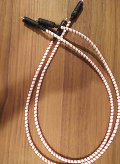
The Parts List :
- signal wire: OCC solid silver 24awg in cotton. 3' per cable
- neutral: OCC solid copper 20awg magnet wire. 2 x 9' per cable
- connectors: KLE pure harmony solid silver
- the white tube is a foamed teflon flexible tube that i ran the signal through. it's pretty amazing. it doesn't kink at all. it's called hyperflex tubing from vh audio
Todd’s Feedback...
I’m still listening to them, but initial findings on the helix ICs are incredibly positive.
More of the helix magic: less noise, greater clarity, better separation of sound sources.
Good stuff!
The HELIX USB Cable
Please Note: this cable does not include the conductor that carry USB supplied power.
- adding a separate cable for this purpose is detailed below
The fabrication of this cable follows the same approach used in the construction of the analogue interconnects and has…
- A twisted pair that carries the D+ and D- digital signals
- NOTE: using the D+ and D- is a differential signalling technique as used in XLR "Balanced" cables.
- A Helix Neutral conductor that is connected to the neutral side of the circuit
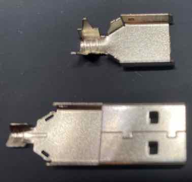
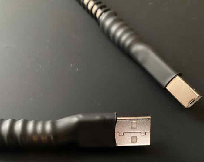
Unfortunately, the TYPE A and TYPE B connectors used are really designed for 24/28 gauge wires and definitely NOT designed for use with the Helix Coil, i.e. without a simple modification
Simply remove the Cable clamps as in the diagrams below
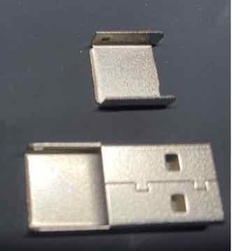
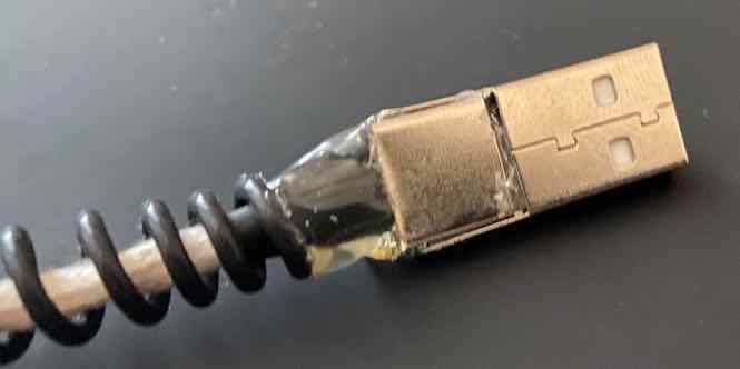
TYPE A USB CONNECTOR
BEFORE AFTER
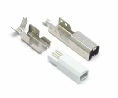
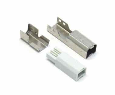
TYPE B USB CONNECTOR
BEFORE AFTER
NOTE: When attaching the wires please ensure you observe the correct pin connections
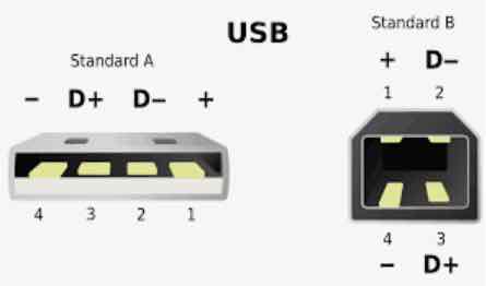
Next, construct the D+ and D- Twisted Pair using a "short twist" as in the image below
- i.e. 3 twists per inch (or per 25mm)
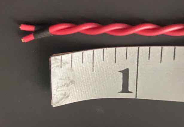
You can use the same 18 gauge wire as used with the Analogue Interconnect, but since there is very little space in the USB connectors the problem of wires shorting out requires extremely precise soldering
The recommended wires for this cable is:
- 18 gauge UP-OCC Solid Silver with AirLok insulation from VH Audio for the signal wire, or
- 18 gauge UP-OCC Solid Copper with AirLok insulation from VH Audio
- 16 gauge Silver Plated Mil-spec for the Helix Neutral (i.e. as used on the Analogue Interconnects)
Please note that either of the signal wires above will perform to a very high level, but for the very best performance, the solid silver wire is preferred
Insert the twisted pair into a piece of cotton tubing with heat-shrink (with adhesive) at each end to hold it in place
Insert that assembly into the Helix Coil and attach the connectors…
Connect one end to the Type A connector.
Stretch the Helix coil to the length of the signal wires
Connect the other end to the Type B connector.
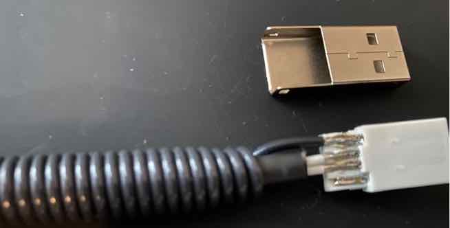
Here is a view of the wires connected to the top of the Type B connector
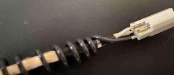
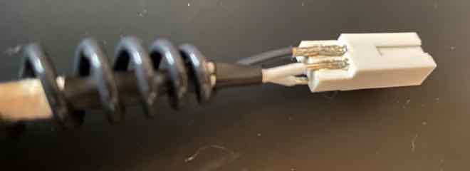
And a view of the wires connected to the Bottom of the Type B connector
Once the wires are soldered in place, Fix the metal housing in place using a hot glue gun.
Be sure to cover the solder joints with hot glue, so as to insulate them from the metal housing
Hot glue the metal cap into place, again covering any solder joints with the glue.
NOTE: Add a little more hot glue to secure the cable assembly to the connector, for strain relief
Do this for both Type A and Type B Connectors
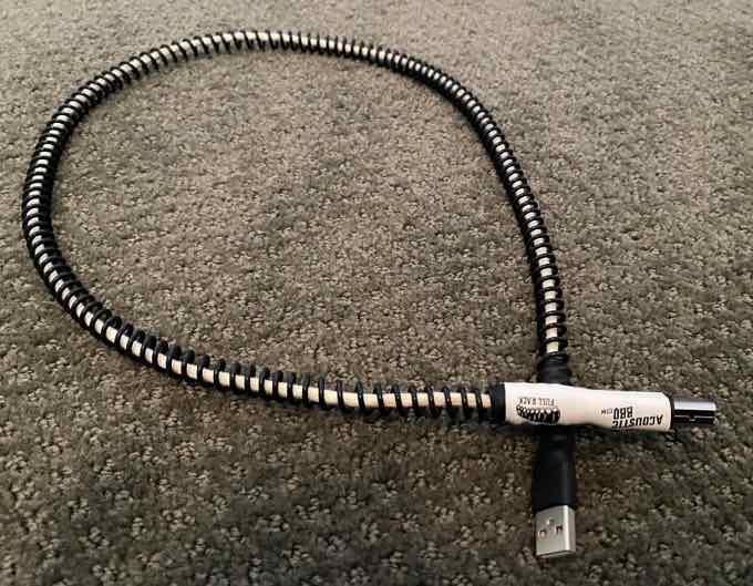
Place two pieces of Heat-shrink (with adhesive) over each connector assembly and the Helix coil to provide additional "strain relief"
NOTE: ensure the Heat Shrink extends onto the Helix Coil by approximately 1.5 inches.
- This prevents the cable from bending and breaking the the delicate solder joints.
And VOILA ! - you have a high performance USB cable
PLEASE NOTE: Before connecting any cable to a component be sure to test the continuity of the pins of each connector
How do I add the Power Supply Wires?
If you would like to add the wire that will provide USB power to the connected device as follows…
- Once the USB connectors have been soldered to the D+ and D- twisted pair BUT before the hot glue has been applied to the connectors
- Cut a length of 18 gauge wire slightly longer than the length of the USB cable
- insert the wire into a piece of braided screen tube (approximately 1" shorter than the piece of wire)
- Then insert the wire and the braided shield into a piece of expandable nylon sleeve (for insulation) and secure with a piece of heat shrink at both ends
- PLEASE NOTE: - the screen is NOT connected to either of the USB connectors
- connect one end of the power wire to the +ve power pin of one connector
- "loosely twist" the power wire assembly around the Helix coil ( i.e. about 4 times around for a 3 ft cable) - this keeps the +ve wire close to the cable
- solder the other end of the +ve wire to the other USB connector
- hot glue the metal casings onto the USB onnectors as detailed above
- Add the two pieces of heat-shrink (with adhesive) over the connector, helix coil and the +ve wire with screen (as shown above)
Audiogon member Grannyring has reported that the Solid Silver conductor from VH Audio provided the highest quality he has ever heard from his USB DAC.